Tree Representations
A new kind of Representation, the Trees, has been defined. Trees allow to bring a hierarchical viewpoint of datas, as they can provide a lot of informations in a clear and concise way. We advice the use of Tree Representations when you can extract an obvious hierarchy out of the information you want to represent in your Viewpoint / Representation.
Any Viewpoint Specifier used to Tables or Diagrams will be able to specify Tree Representations quite easily, as standard notions and tools have been reused.
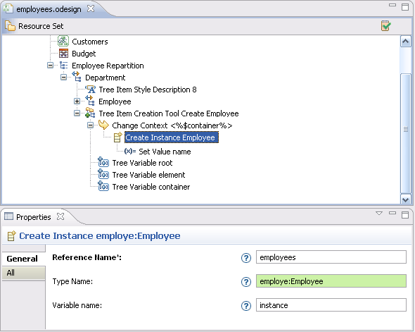
Trees offer a lot of features improving usability, such as :
- Custom Drag and Drop specification
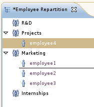
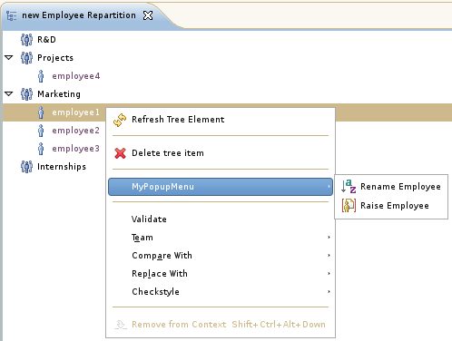
- Direct Edit, Navigation Tools, Creation Tools, Deletion Tools...
A complete documentation, including Reference guide and a quickstart based on a concrete example will allow you to quickly get used with this new kind of Representation.
Sequence Diagrams Representations
- Sequences Diagrams with all the complex constructions (inspired from UML)
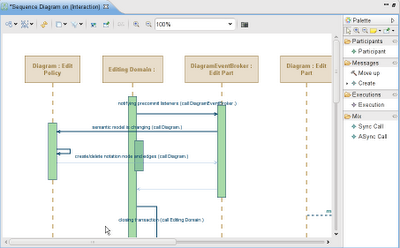
- Adaptable to any DSL
- Advanced management of combined fragment
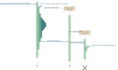
Diagram Editor
Show/Hide labels
It is now possible to hide the edge label and the node label if it is on the border of its node.
The «Diagram elements visibility» wizard considers now the labels of the nodes and edges.
Node label
The approach is the same as for other elements, except that there is a specific menu named «Hide/Show Label». It is possible to call this menu directly on the node or on its label.
Four ways to hide or reveal labels :
- from the context menu on the node or its label
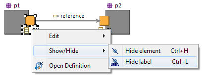
- from the tabbar, an new icon appears on the selection of the node or its label
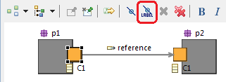
- from the outline view, selecting the node or its label
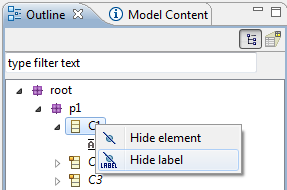
- from the «Diagram elements visibility» wizard
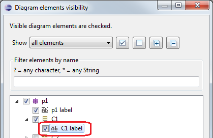
Edge label
Same approach than the node label with specifics menus «Hide/Show Label» called on the edge or its label.
Four ways to hide or reveal labels :
- from the context menu on the edge or its label

- from the tabbar, an new icon appears on the selection of the edge or its label
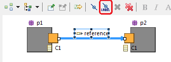
- from the outline view, selecting the edge or its label
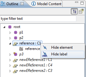
- from the «Diagram elements visibility» wizard
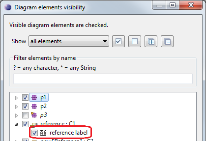
Transversal
Specifying Colors
It is now possible to choose as many colors as you want by adding Color Step children to the Interpolated Color. The previous mechanism (From Green to Red) is still operational.
Here is the .odesign definition:
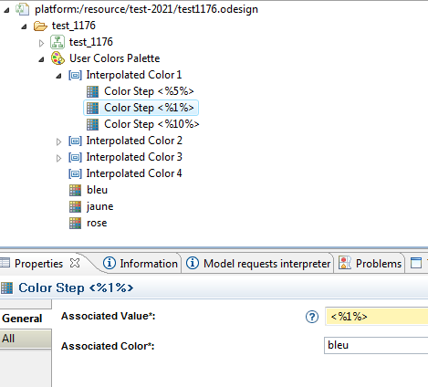
And here is the result:

It is possible to define a new color type with computed RGB. Each color component can be defined by an expression (Acceleo, OCL, or another specific interpreter). This evolution is needed for a specific diagram in which the color of the element depends on the semantic model.
Here is the .odesign definition:

Editors
Eclipse Editors from Viewpoints
You have now the possibility to create easily a specific eclipse editor for a given representation description. When opening the editor will automatically create the session at opening and dispose it at closing.
A thin Eclipse compatibility layer has been added to allow you to define a real Eclipse editor from your Viewpoints:
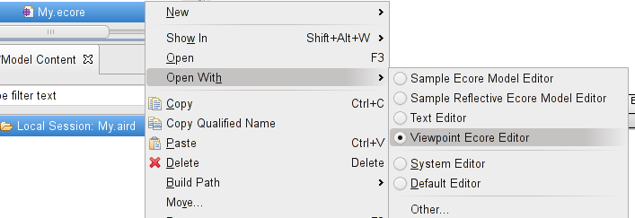
With this editor available through a right click the session is completely managed for your users.
End User documentation
You have now the possibility to document the Viewpoint, Representation Description and Layer for the end-user.
Documentation of Viewpoint:
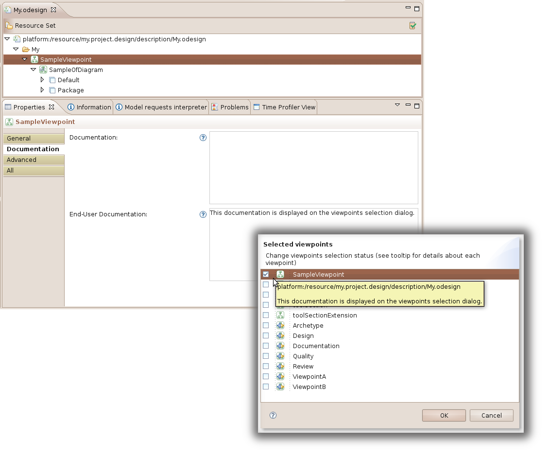
Documentation of Representation:
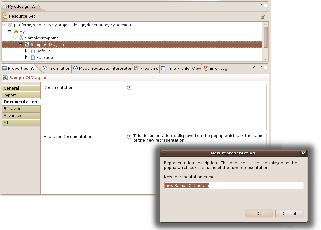
Documentation of Layer:
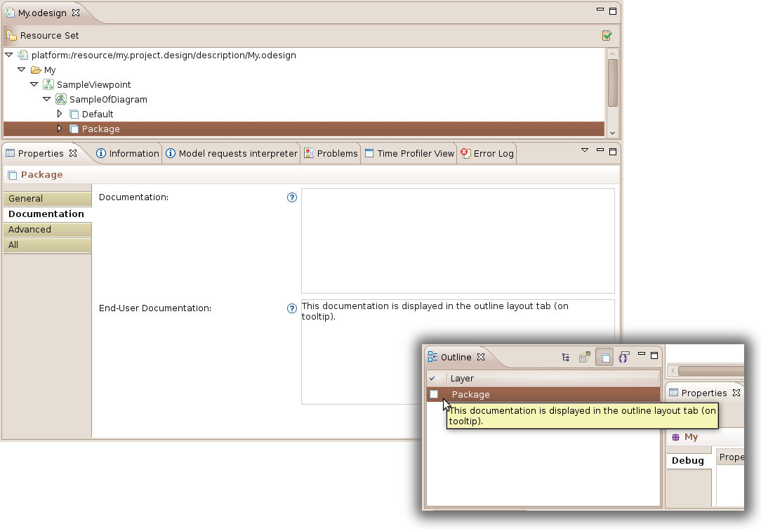
Diagram Representations
ToolFilter
You have now the possibility for tools to be hidden in the palette based on a precondition. You can specify semantic element features to listen to trigger precondition computation and update of the palette accordingly.
Edge mapping
The notion of edge mappings is divided into two types:
- Element based edge: replaces an edge mapping with domain based
- Reference Based Edge: replaces an edge mapping without domain based
Two actions are now available to create these mappings:
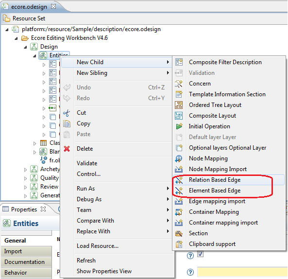
The tabbed property «Domain Based» no longer exists : the check box «Domain based» disappears and the «Semantic Candidates Expression», «Source Finder Expression» and «Domain class» properties exist only for element based edge, not for relation based edge. These fields are now in the general tab.

Diagram Editor
New user interface
Tab bar
For each diagram, a tab bar is displayed with content depending on the selection.


Layers and filters management
Activation of layers and filters could be directly done from the diagram tab bar instead of the outline view.
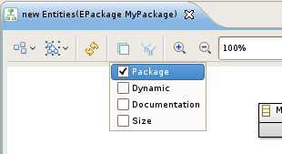
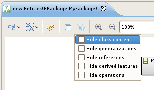
Contextual menu simplification
Some old or not very used items have been removed from the contextual menu.
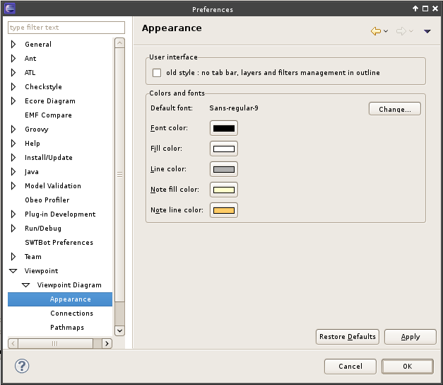
If you do not like the new user interface, or have a problem with the new one, you could re-enable the old one through the preferences:
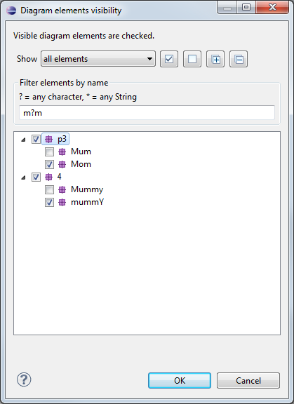
Show/Hide elements using a tree viewer
A new button, named Show/Hide is accessible on the tab bar.

This open a dialog that display the diagram elements as a tree. This way the user can choose shown and hidden elements more easily.
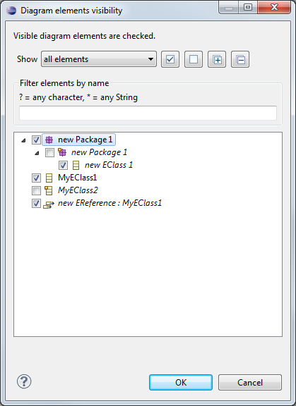
User will be able to filter elements to show/hide using standard Regular Expressions:
Pin/Unpin elements using a tree viewer
A new button, named Pin/Unpin is accessible on the tab bar.

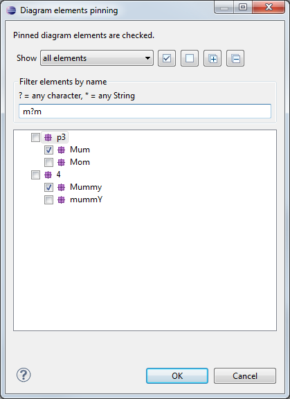
This open a dialog that display the diagram elements as a tree. This way the user can choose the elements to pin or unpin more easily.
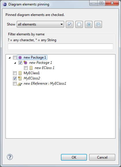
User will be able to filter elements to pin/unpin using standard Regular Expressions:
Hiding icons of labels on Shapes or Connectors
New options in the Viewpoint Diagram preferences (Window/ Preferences/ Viewpoint/ Viewpoint Diagram/ Appearance) will allow user to hide all icons of the labels on Shapes or Connectors.
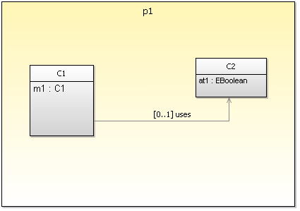
For example, if the user has checked both "Hide label icons on shapes" and "Hide label icons on connectors" options, the following diagram:
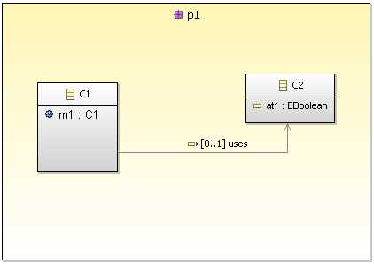
will become (once re-opened):
Quick outline
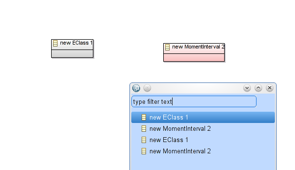
- There is now a new context menu action on diagrams Quick outline, also accessible with CTR O to search and navigate into diagram elements.
Properties
There is a new tab in the Properties view of the diagram itself (no selected element) named Documentation. This tab provides a text area for the diagram documentation.
Node label
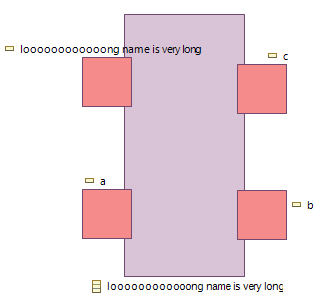
The border label of a node is now centered if placed on south or north border and larger than the width of the node.
Container label
There is a new label option in the label tab : label border style.

As a result a border will be drawn around the container label.

Labels color
The color of the label in the style description of a mapping can now be defined with based colors but also with interpolated colors and fixed colors. By default, the color will be black.

Collapse behavior
When a border node is collapsed, the corresponding figure is minimized (size : 4pix * 4pix) and transparent. Selection and move of collapsed border nodes are enabled.
Batch images export
The Batch images export now can export images in PNG and SVG format.
Model Splitting
There is a new preference on the Viewpoint page : Always create an aird fragment on control. This preference allow the creation of an empty aird fragment if there is no representation selected during a control.
Compatibility
Migrating from 4.6
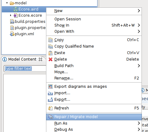
You should migrate all your Viewpoint Specification Models (*.odesign) first using the contextual action in the popup menu.
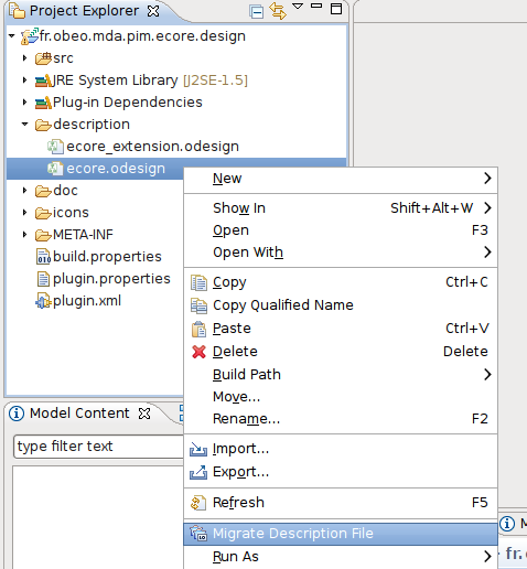
Make sure your migrated model is still valid using the validation action , at the top right corner of the editor.
Once your .odesign are migrated you should migrate the Representation Data (*.aird) using the contextual action in the popup menu.
Manual migration for rounded corners styles
A change in the way Viewpoint interprets the arcWdith and arcHeight attributes for rounded corner styles requires a manual migration of the VSM. This will not be done by the automatic migration operation.
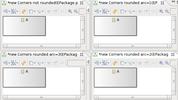
For diagram elements which have rounded corners (as specified in their style element in the VSM), the arcWidth and arcHeight attributes indicate the size of the rounding. In Viewpoint 4.6.x, that size was incremented in big steps each time the attributes were incremented, as seen in the screenshot below (respectively with no rounding, and rounding with arc sizes of 1, 2 and 3):

Viewpoint 5.2 interprets the arcWidth and arcHeight differently to give a much finer control on the size of the rounding. However, this means that if the styles in the VSM is not modified, the previous small values of 1, 2 and 3 (for example) will give the impression that rounded corners do not work anymore. In order to obtain the same visual result as before, the arcWidht and arcHeight must be multiplied by 25. The two screenshots below show a non-modified VSM in Viewpoint 5.2 (rounding of 1, 2 or 3 are so small that they look not rounded at all), and a modified VSM where the arc sizes have been multiplied by 25, to obtain the same visual result as before.

Of course, specifiers can now choose intermediate values (non multiple of 25) to obtain finer control on the rounding size.
|


